– FIG.26
– FIG.27
– FIG.35N
– FIG.35R
THREADED END AIR VALVE FIG.25
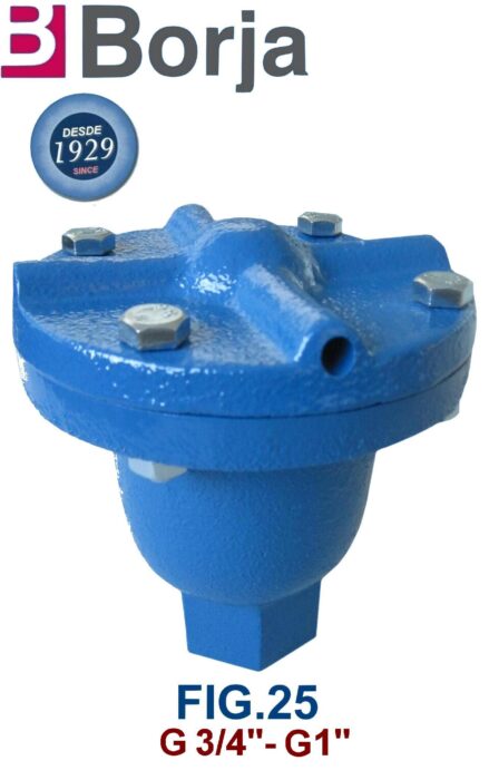
- In cast iron construction.
- Threaded ends according to: DIN 259.
- Download pdf: FIG.25 THREADED.pdf
AIR VALVE WITH FLANGE FIG.26

- In cast iron construction.
- Flange dimensions and holes according to UNE-EN 1092-2 PN10 / PN16.
- Download pdf: FIG.26.pdf
AIR VALVE THREADED END FIG.26
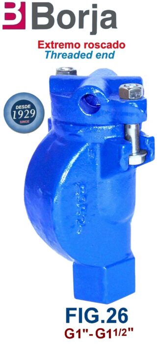
- Construcción en fundición gris.
- In cast iron construction.
- Extremos roscados según: DIN 259.
- Download pdf: FIG.26 THREADED.pdf
DOUBLE FUNCTION AIR VALVE WITH FLANGE FIG.27
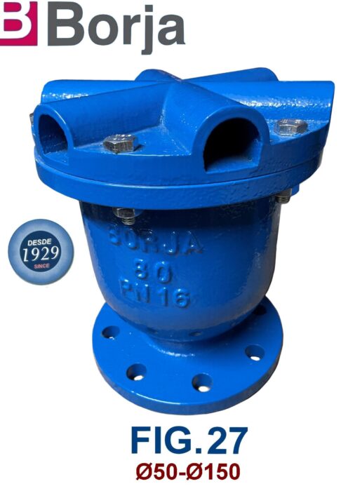
- In cast iron construction.
- Flange dimensions and holes according to: UNE-EN 1092-2 PN10 / PN16.
- Download pdf: FIG.27.pdf
THREADED END DOUBLE FUNCTION AIR VALVE FIG.27
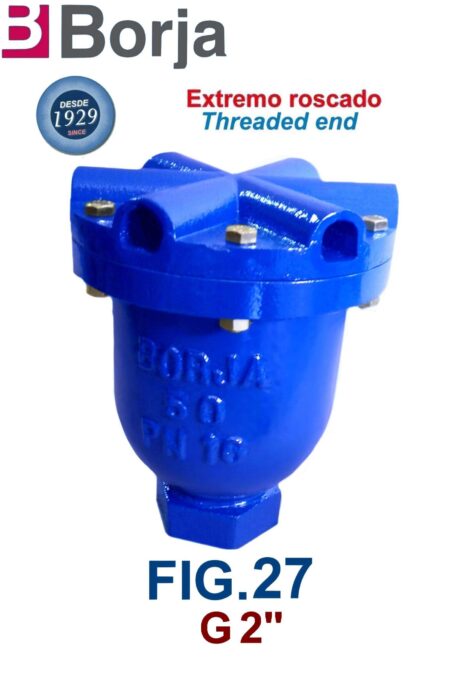
- Construcción en fundición gris.
- Extremo rosca según DIN 259.
- Download pdf: FIG.27 THREADED.pdf
TRIFUNCTIONAL AIR VALVE WITH FLANGE FIG.35N
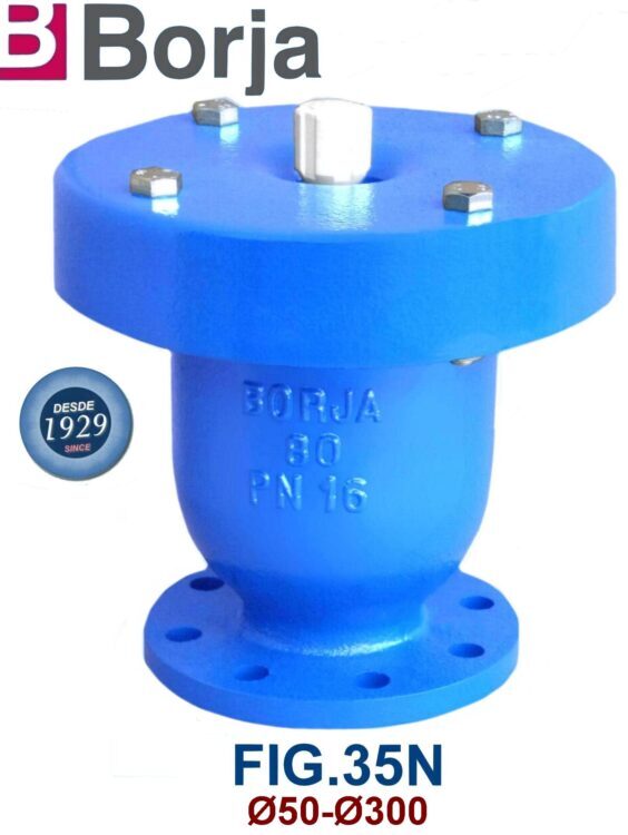
- In ductile iron construction.
- Flange dimensions and holes according to: UNE-EN 1092-2 PN16.
- Holes dimensions according to: UNE-EN 1092-2 PN10 / PN16.
- To can work correctly, the minimum working pressure should be at least 1.5 bar.
- Download pdf: FIG.35N.pdf
THREADED END TRIFUNCTIONAL AIR VALVE FIG.35N
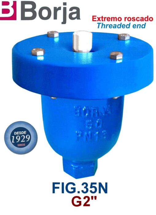
- In ductile iron construction.
- Threaded end according to DIN 259.
- To can work correctly, the minimum working pressure should be at least 1.5 bar.
- Download pdf: FIG.35N THREADED.pdf
SEWAGE WATER TRIFUNCTIONAL AIR VALVE FIG.35R
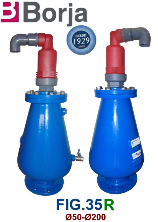
- In cast iron construction.
- Flange and holes dimensions according to: UNE-EN 1092-2 PN10 / PN16.
- To can work correctly, the minimum working pressure should be at least 1.5 bar
- Download pdf: FIG.35R.pdf
