– FIG.14
– FIG.18
FOOT VALVE FIG.14


- In cast iron construction. The valve Ø600 only available in ductile iron construction.
- Flange dimensions and holes according to: UNE-EN 1092-2 PN10.
- Maximum working pressure 10 m.w.c. (1 bar).
- From Ø 40 to Ø150 simple seal disk.
- From Ø 200 to Ø600 double seal disk.
- Download pdf: FIG.14.pdf
FOOT VALVE FIG.18
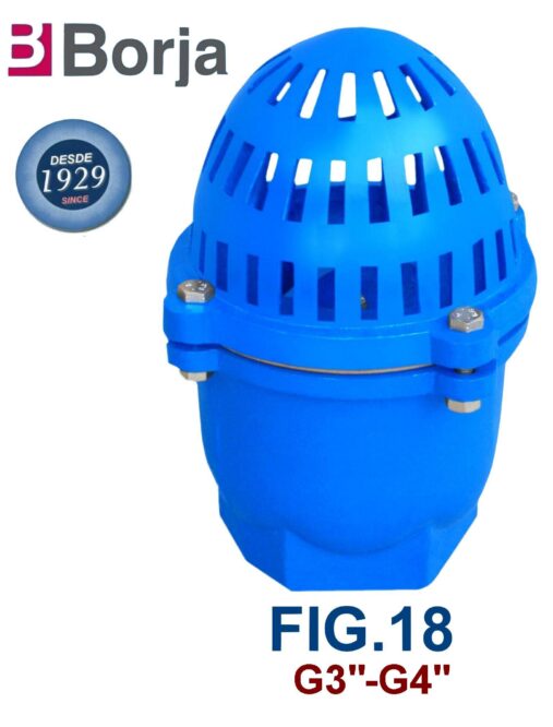
- In cast iron construction.
- Download pdf: FIG.18.pdf
FOOT VALVE FIG.54
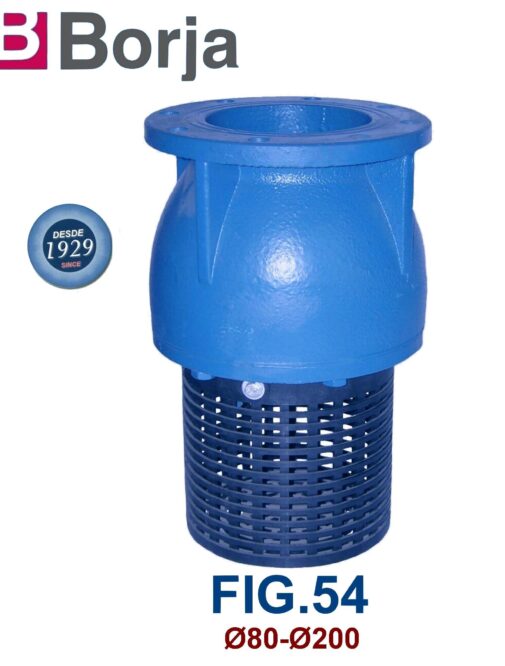
- In cast iron construction.
- The valve FIG.54 is the same valve FIG.56 with especial drilled in flange.
- Download pdf: FIG.54.pdf
FOOT VALVE FIG.56
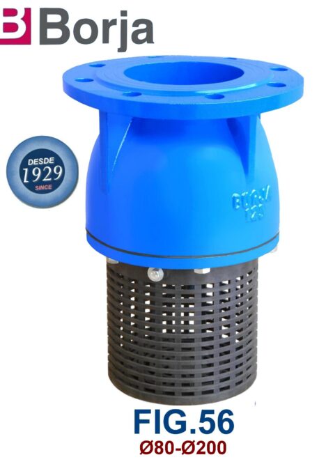

- In cast iron construction.
- Flange dimensions and holes according to: UNE-EN 1092 PN10.
- Download pdf: FIG.56
