– FIG.13N
– FIG.19
– FIG.37
– FIG.39
– FIG.40
– FIG.41
– FIG.44
– FIG.78
CHECK VALVE EN-12334 FIG.13
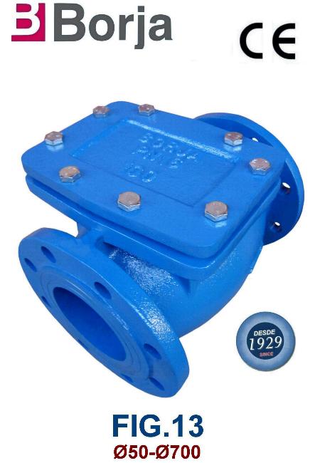
- According to EN-12334.
- In cast iron construction.
- Flanges dimensions according to UNE-EN 1092-2 PN16
- Holes dimensions according to UNE-EN 1092-2 PN10 / PN16.
- Download pdf: FIG.13.pdf
CHECK VALVE EN-12334 FIG.13N

- According to EN-12334.
- In ductile iron construction.
- Flanges dimensions according to UNE-EN 1092-2 PN25
- Holes dimensions according to UNE-EN 1092-2 PN16 / PN25.
- Download pdf: FIG.13N.pdf
DISK CHECK VALVE EN-12334 FIG.19
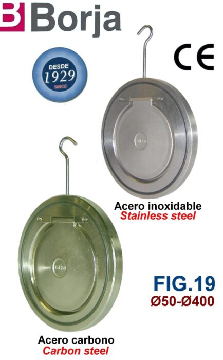
- According to EN-12334.
- In carbon steel or stainless steel construction.
- Valve for mounting between flanges according to UNE-EN 1092-2 PN10 / PN16.
- These valve from Ø100 to Ø400 are also suitable for mounting between flanges according to ANSI Class 150 lbs.
- Maximum working temperature NBR 80 ºC.
- Download pdf: FIG.19.pdf
DUAL PLATE CHECK VALVE EN-12334 FIG.37
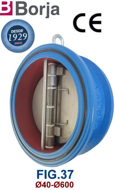
- According to EN-12334.
- In cast iron construction.
- Face to face dimensions according to EN 558-1 Serial F16. API 609 BS 3135.
- Valve for mounting between flanges according to UNE-EN 1092-2 PN10 / PN16.
- These valve from Ø100 to Ø600 are also suitable for mounting between flanges according to ANSI Class 150 lbs.
- Maximum working temperature NBR 80 ºC.
- Download pdf: FIG.37.pdf
DUAL PLATE CHECK VALVE EN-12334 FIG.37 STAINLESS STEEL

.
- According to EN-12334.
- Stainless steel construction.
- Face to face dimensions according to EN 558-1 Serial F16.
- Valve for mounting between flanges according to UNE-EN 1092-2 PN10 / PN16 / PN25 / PN40 / ANSI 150 / 300 Lbs.
- Download pdf: FIG.37 STAINLESS STEEL.pdf
DOUBLE DISK CHECK VALVE EN-12334 FIG.37 PN25
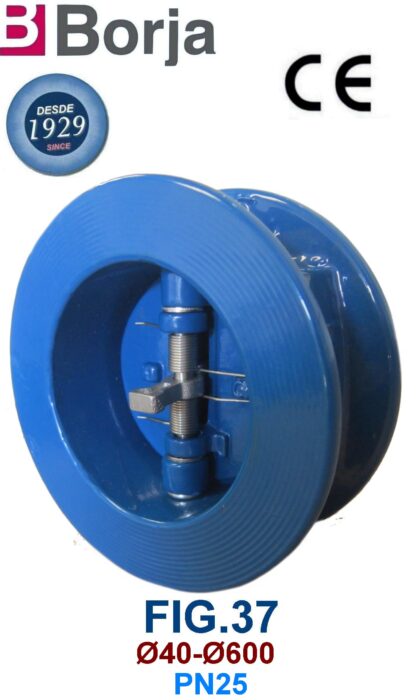
- According to EN-12334.
- In ductile iron construction.
- Face to face dimensions according to EN 558-1 Serial F16. API 609 BS 3135.
- Valve for mounting between flanges according to UNE-EN 1092-2 PN25.
- Download pdf: FIG.37 PN25.pdf
AXIAL CHECK VALVE WITH FLANGES FIG.39
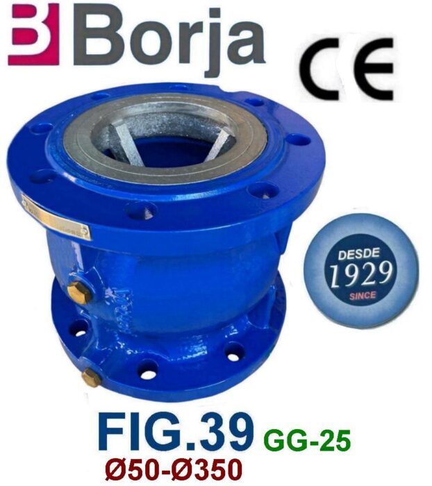
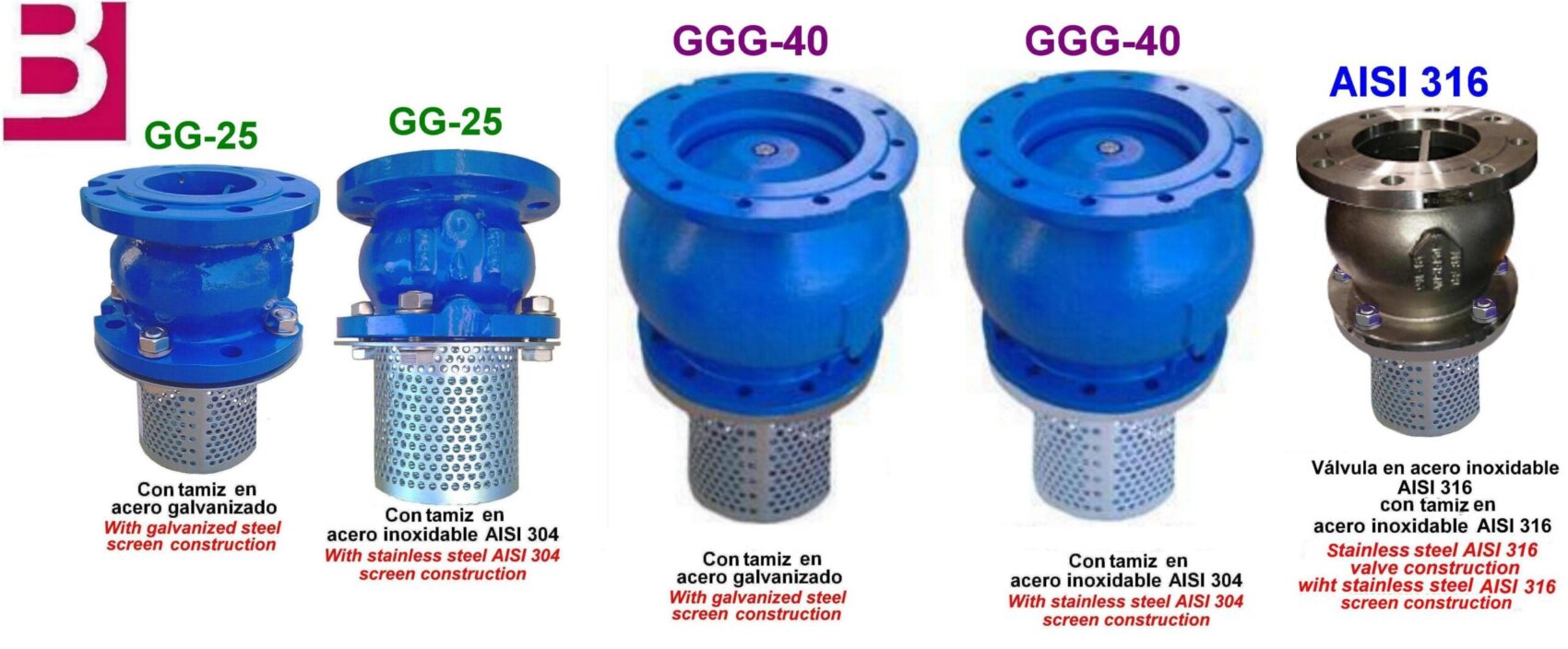
- In cast iron construction (Body) and ductile cast iron construction (Disk, Guide)
- Flange dimensions according to UNE-EN 1092-2 PN 16
- Holes dimensions according to UNE-EN 1092-2 PN 10 / PN16.
- NBR temperature: From -10 to +80 ºC.
- Option: the whole manufacturing in ductile iron with flange dimension and holes according to UNE-EN 1092-2 PN 16 / PN 25 or ANSI Class 150. Both constructions (castiron and ductile iron) have the screen option in galvanized steel or stainless steel AISI 304.
- Option (From Ø100 to Ø300): the whole manufacturing in stainless steel AISI 316 with flange dimension and holes according to UNE-EN 1092-2 PN 16 / PN 25 or ANSI Class 150 with stainless steel AISI 304 screen option.
- Download pdf: FIG.39.pdf
BALL CHECK VALVE EN-12334 FIG.40

- According to EN-12334.
- In ductile iron construction.
- Face to face dimensions according to EN 558-1 Serial F48.
- Flanges dimensions and holes according to UNE-EN 1092-2 PN16.
- Internal and external “EPOXY“ coating RAL 5017.
- Working conditions: From -1 to +10 bar, from -10 to +80 ºC.
- Download pdf: FIG.40.pdf
SIMPLE DISK WAFER TYPE CHECK VALVE EN-12334 FIG.41

- According to EN-12334.
- Stainless steel construction.
- Face to face dimensions according to EN 558-1 Serial F49
- Valve for mounting between flanges according to UNE-EN 1092-2 PN16 / PN25 / PN40 and ANSI 150 / 300 Lbs.
- Download pdf: FIG.41.pdf
THREADED ENDS BALL CHECK VALVE EN-12334 FIG.44

- According to EN-12334.
- In ductile iron construction.
- Threaded ends according to DIN 259
- Download pdf: FIG.44.pdf
VALVE EN-12334 FIG.78

- According to EN-12334.
- In cast iron construction.
- Face to face dimensions according to EN 558-1 Serial F1.
- Flanges dimensions and holes according to UNE-EN 1092-2 PN16.
- Working temperature: -10 ºC to 200 ºC.
- Download pdf: FIG.78.pdf
